3.FM Radio
##Case Description
Simulate a radio where specific "radio station" tones are received only when the knob is adjusted to a designated scale.
###Key Knowledge Points
- Master the usage of the Sugar potentiometer module.
- Master the usage of the 【Mapping】 block.
Case Implementation
Structural Assembly
Circuit Connection
• Connect the Sugar potentiometer module to the Robotbit P1 terminal block.
• Connect the servo's 3-pin wire to the S1 port according to the corresponding colors.
Programming
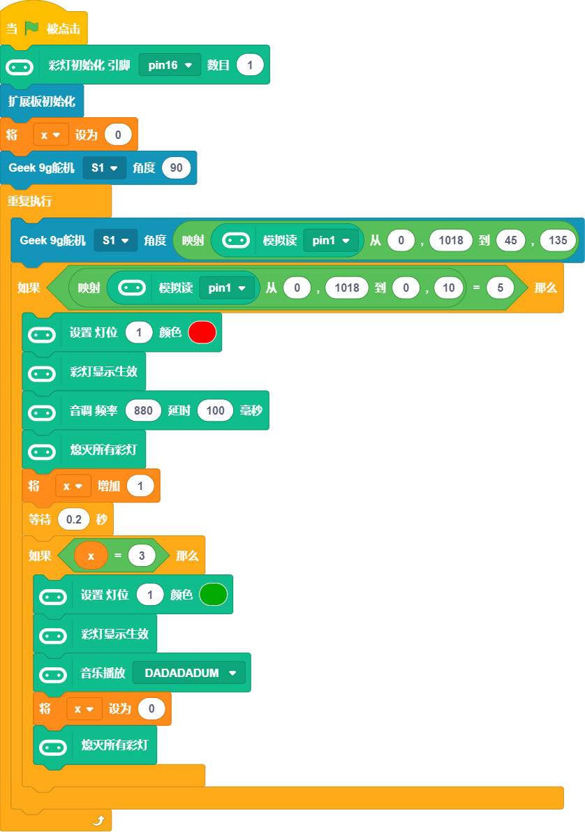
- The RGB light pin on RobotbitEdu is connected to P16 by default, so RGB light initialization is required. 2.The servo is used, so [Expansion Board Initialization] is also required.
3.Use the servo to simulate the radio display pointer, which moves with the potentiometer, using the 【Mapping】 block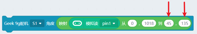
4.Simultaneously map the potentiometer value to 0~10. When the value is 5, it indicates that the corresponding channel is received, and the corresponding buzzer sound is played.
The program is as follows: